This equipment is operated by a robust and reliable PLC system housed in a NEMA4X control panel.

Key Specs:
Flow Rate
100 to 3000 scfm
Connection
¾” NPT (F) to 6" Flg
Air Quality
ISO 8573.1:2010 Class 1.2.2 or 1.1.2
Product Documentation
- Brochures
- Electrical Diagrams
- Flow Diagrams
- General Arrangement Drawings
- Material Safety Data Sheets
- Spare Parts List
- User Guide
- With Pre & After Filters
- With Pre & After Filters
Features
Our energy-saving dew point control option provides the ultimate in energy and power savings and reduces dryer wear and tear.
ASME code pressure vessels, UL/cUL compliant, made in the USA activated alumina, lifting lugs and/or fork lift pockets
Specifications of Our Models
Dryer Models |
Recommended Pre & After Filtration |
Inlet & Outlet |
Rated Flow at 100 psig |
|
|---|---|---|---|---|
Prefilter |
After Filter |
NPT (F) / FLG |
scfm |
|
GFN 0085 M01 |
GFN 0085 M1 |
¾" |
70 |
|
GFN 0105 M01 |
GFN 0105 M1 |
1" |
100 |
|
GFN 0175 M01 |
GFN 0175 M1 |
1" |
150 |
|
GFN 0325 M01 |
GFN 0325 M1 |
1 ½" |
200 |
|
GFN 0325 M01 |
GFN 0325 M1 |
1 ½" |
250 |
|
GFN 0325 M01 |
GFN 0325 M1 |
1 ½" |
300 |
|
GFN 0450 M01 |
GFN 0450 M1 |
2" |
350 |
|
GFN 0450 M01 |
GFN 0450 M1 |
2" |
450 |
|
GFN 0700 M01 |
GFN 0700 M1 |
2" |
500 |
|
GFN 0700 M01 |
GFN 0700 M1 |
2" |
600 |
|
GFN 0850 M01 |
GFN 0850 M1 |
2" |
750 |
|
GFN 1250 M01 |
GFN 1250 M1 |
3" Flg |
1000 |
|
GFN 1250 M01 |
GFN 1250 M1 |
3" Flg |
1250 |
|
GFN 1500 M01 |
GFN 1500 M1 | 3" Flg |
1500 |
|
| HL2000 | NFZ 2500 M01 | NFZ 2500 M1 | 4" Flg | 2000 |
| HL2500 | NFZ 2500 M01 | NFZ 2500 M1 | 4" Flg | 2500 |
| HL3000 | NFZ 3500 M01 | NFZ 3500 M1 | 6" Flg | 3000 |
Specifications |
Standard |
Optional |
|---|---|---|
Maximum particle size (ISO class) |
class 2 |
- |
Maximum water content (ISO class) |
class 2 |
- |
Minimum / design / maximum operating pressure range (HL0070 to HL1500) |
60 / 100 / 180 psig |
- |
Minimum / design / maximum operating pressure range (HL2000 to HL3000) |
60 / 100 / 135 psig |
- |
Minimum / design / maximum ambient temperature |
38 / 100 / 120°F |
20 / 100 / 120°F |
Minimum / design / maximum inlet temperature |
38 / 100 / 120°F |
- |
| Power supply requirements | 115V / 1Ph / 60Hz | 230V / 1Ph / 60Hz & 12V DC |
(1) This information is for general information purposes only. For additional technical specifications, refer to the product brochure, technical data sheets, and/or user guides. Technical specifications are subject to change.
Frequently Asked Questions
A desiccant dryer is a type of compressed air dryer that removes moisture from compressed air using a desiccant material—typically silica gel, activated alumina, or molecular sieves. These materials attract and hold water vapor from the air, ensuring the output is extremely dry. You need a desiccant dryer when moisture in compressed air could cause problems or damage, such as: precision manufacturing, pneumatic tools and valves, food processing, pharmaceutical, paint spraying, cold environments. In cold climates, a desiccant dryer is required to prevent moisture in compressed air lines from freezing. They are essential when ultra-dry air is required, typically reaching dew points as low as -40°F to -94°F.
Dew point is the temperature at which air becomes saturated with moisture, meaning it can no longer hold all the water vapor it contains. When air is cooled to its dew point, water vapor starts to condense into liquid water. On a humid day, the dew point might be 65°F. If the temperature drops to that level overnight, dew forms on surfaces.
In compressed air systems, if the dew point is higher than pipe or ambient temperatures, condensation will form inside the system, leading to corrosion or contamination.
Pressure Dew Point (PDP) is the temperature at which water vapor begins to condense into liquid at a given system pressure (not atmospheric pressure). It's a key measure of how dry compressed air is.
In compressed air systems, moisture is your enemy — it causes:
- Corrosion in pipes and tools
- Malfunction of pneumatic equipment
- Product contamination (especially in food, pharma, electronics)
Yes. Climate and environmental conditions directly affect the amount of moisture in the air and the risk of condensation in your compressed air system. This, in turn, affects the dew point you need to maintain to avoid moisture-related issues.
- Hot & Humid Climates
- Higher ambient humidity means more water vapor in the air.
- You’ll need a lower dew point to remove moisture and avoid effectively:
- Water buildup in lines
- Corrosion
- Product contamination
- Typical PDP required: -40°F (or lower for sensitive applications)
- Cold Climates
- Moisture can condense and freeze in outdoor lines or exposed piping.
- Even if the air contains less moisture, freezing becomes a concern.
- A dew point lower than the coldest ambient temperature is essential.
Rule of thumb: Set PDP at least 20°F below the lowest ambient temperature the system will encounter.
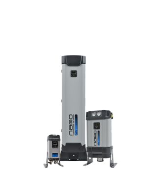
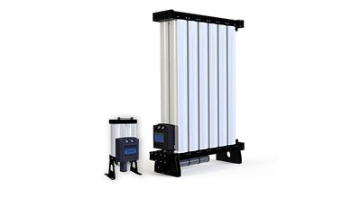
The HL range utilizes a two-tower system, where one tower dries the compressed air, and the other undergoes regeneration using a portion of the dried air. This heatless regeneration process ensures continuous operation without the need for external heat sources. The system employs strategically positioned valves to switch between drying and regeneration cycles.
The HL dryers provide a standard pressure dew point (PDP) of -40°F, which corresponds to approximately 0.1% relative humidity at room temperature, suitable for most industrial applications. For more demanding environments, an our CDP Critical Dewpoint Dryer range offers -94°F PDP, delivering ultra-dry air that is virtually free of moisture. This lower dew point is crucial for critical applications where even minute traces of moisture can lead to problems such as corrosion, bacterial growth, or product contamination. Typical industries requiring a -94°F PDP include pharmaceutical manufacturing, semiconductor manufacturing, aerospace, and cleanroom laboratories. However, unless your application demands explicitly ultra-low humidity, a -40°F dew point is a more cost-effective and energy-efficient choice.
Moisture is adsorbed by the desiccant (activated alumina) as compressed air flows through the drying tower. The regeneration tower then uses a small amount of the dry air to remove moisture from the saturated desiccant.
1. Determine required air flow (measured in standard cubic feet per minute, scfm)
2. Know your inlet conditions, as your dryer performance depends on the actual conditions of the air entering the dryer.
- Inlet Temperature (°F)
- Inlet Pressure (psig)
- Ambient Temperature (°F) – where the dryer is located
3. Select the required pressure dew point (PDP).
- -40°F: general industrial use (standard)
Yes, but only a minimal power supply is needed—for the controller and solenoid valves.
Typically, 15–20% of the dried air is used for regeneration. This is a trade-off for not using heat during the regeneration phase.
- NEMA 4X control panel
- Mounted pre and after filters
- Adjustable purge valve
- UL/CUL Compliant
- Various bypass options
- Electrical protection upgrades (NEMA 7, Z-purge).
- Dew point monitors (integral or portable).
- Stainless steel control tubing.
- Low ambient temperature protection
- Visual moisture indicators.
- Run time hour meters.
- Additional pressure and temperature gauges
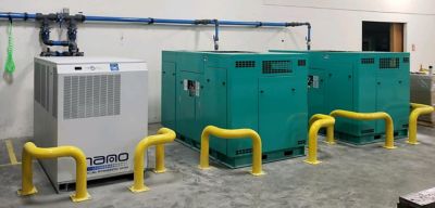
HL series desiccant dryers are equipped with corrosion-resistant NEMA 4X electrical enclosures as standard, making them suitable for outdoor and harsh environments. However, additional modifications—such as a low ambient package and stainless steel control lines—are often recommended to ensure optimal performance and durability in extreme conditions.
Yes, all HL desiccant dryers undergo comprehensive quality assurance procedures, including complete functional testing, pressure and leak testing, and verification of the control system before shipment. This ensures each unit meets performance specifications and is ready for reliable operation upon installation.
- Desiccant replacement (every 3–5 years, depending on use)
- Filter (control air, inlet and outlet) & Muffler annual replacement
- Valve inspection
- Checking for desiccant dusting or channeling
The cost varies depending on the flow rate and pressure dew point (PDP) required for your compressed air system.
Period: 18 months from date of shipment from the factory or 12 months from date of installation/start up, whichever occurs first • Coverage: 100% parts and labor per defined service time allowances • Extended coverage: Inlet & purge exhaust valves: 5 years from date of shipment (parts only)