Drawing")
 Drawing")
 - GA Drawing")
 - GA Drawing")
 Drawing")
 Drawing")
 Drawing")
 Drawing")
 Drawing")
 Drawing")
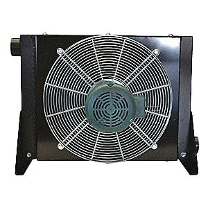
We’ve constructed our X-CC fin and tube designs to be up to 60% smaller than other conventional components on the market
Key Specs:
Flow Rate
100 to 3500 scfm
Operating Temperatures
35 to 250°F
Max Allowable Working Pressure
250 psig
Product Documentation
- Brochures
- General Arrangement Drawings
Features
Available 7 motor configurations to meet all application needs
Heresite core for corrosion protection, water separator for removing condensate
Specifications of Our Models
Specifications |
|
|---|---|
Maximum working pressure |
250 psi |
Maximum working temperature |
250°F |
Cooler material |
aluminum |
Shroud material |
powder painted steel |
Fan guard material |
zinc plated steel |
Fan blade material |
polypropylene blades/aluminum hub |
Mounting brackets |
powder painted steel |
ROTARY COMPRESSOR |
||
|---|---|---|
Air Compressor |
Internal Air Flow |
Recommended X-CC Model |
Horsepower |
Maximum cfm |
|
20 hp |
113 |
X-CC 100 |
25-40 hp |
245 |
X-CC 200 |
50-75 hp |
539 |
X-CC450 |
100-125 hp |
785 |
X-CC 600 |
150-200 hp |
1569 |
X-CC 1000 |
225-350 hp |
2300 |
X-CC 1600 |
400-500 hp |
3016 |
X-CC 2000 |
550-700 hp |
4316 |
X-CC 2500 |
750-1000 hp |
4800 |
X-CC 3500 |
PISTON COMPRESSOR |
||
|---|---|---|
Air Compressor |
Internal Air Flow |
Recommended X-CC Model |
Horsepower |
Maximum cfm |
|
20 hp |
83 |
X-CC 100 |
25-30 hp |
181 |
X-CC 200 |
40-70 hp |
432 |
X-CC450 |
75-100 hp |
638 |
X-CC 600 |
125-200 hp |
1256 |
X-CC 1000 |
225-300 hp |
2133 |
X-CC 1600 |
350-400 hp |
3400 |
X-CC 2000 |
400-500 hp |
4458 |
X-CC 2500 |
700-850 hp |
4800 |
X-CC 3500 |
MOISTURE SEPARATORS |
||
|---|---|---|
Aftercooler |
Separator |
Series Maximum Capacity |
X-CC 100 |
NF 0175 WS |
X-CC 100 |
X-CC 200 |
NF 0325 WS |
X-CC 200 |
X-CC450 |
NF 0700 WS |
X-CC450 |
X-CC 600 |
NF 0700 WS |
X-CC 600 |
X-CC 1000 |
NF 1250 WS |
X-CC 1000 |
X-CC 1600 |
NF 1500 WS |
X-CC 1600 |
X-CC 2000 |
NFE 3000 WS-ND |
X-CC 2000 |
X-CC 2500 |
NFE 3000 WS-ND |
X-CC 2500 |
X-CC 3500 |
NFE 3000 WS-ND |
X-CC 3500 |
Electrical Motor Data |
||||||||
|---|---|---|---|---|---|---|---|---|
Model |
HP RPM |
Motor Frame |
Single Phase |
Three Phase |
||||
Voltage |
Hz |
Full Load amps 230V |
Voltage |
Hz |
Full Load amps 230V |
|||
X-CC 100 |
⅓ 3450 |
IEC 63 |
115/230 |
60 |
2.6 |
208-230/460 190/380 |
60 50 |
1.1 |
X-CC 200 |
½ 3450 |
IEC 71 |
115/230 |
60 |
3.5 |
208-230/460 190/380 |
60 50 |
1.6 |
X-CC450 |
½ 1725 |
NEMA 56C |
115-230/460 |
60 |
4.0 |
208-230/460 |
60* |
2.0 |
X-CC 600 |
1 1725 |
NEMA 56C |
115-230/460 |
60 |
6.4 |
208/230/460 |
60* |
3.8 |
X-CC 1000 |
2 1725 |
NEMA 56C |
115/230 |
60 |
9.2 |
208-230/460 |
60* |
6.2 |
X-CC 1600 |
5 1725 |
NEMA 184TC |
230 |
60 |
23 |
208-230/460 |
60* |
13.2 |
X-CC 2000 |
7 ½ 1725 |
NEMA 213TC |
CF |
CF |
CF |
208-230/460 |
60* |
19.6 |
X-CC 2500 |
7 ½ 1725 |
NEMA 213TC |
CF |
CF |
CF |
208-230/460 |
60* |
19.6 |
X-CC 3500 |
10 1725 |
NEMA 213TC |
CF |
CF |
CF |
208-230/460 |
60* |
26.0 |
Air Motor Data |
||||
|---|---|---|---|---|
Model |
Air Pressure to Motor (psi) |
Motor Air Consumption (cfm) |
Air Motor Connection Size |
Fan RPM |
X-CC 100 |
30 |
10 |
¼” NPT |
3450 |
X-CC 200 |
60 |
17 |
¼” NPT |
3450 |
X-CC450 |
40 |
25 |
¼” NPT |
1725 |
X-CC 600 |
40 |
¼” NPT |
1725 |
|
X-CC 1000 |
60 |
70 |
½” NPT |
1725 |
X-CC 1600 |
60 |
150 |
1 ¼” NPT |
1725 |
X-CC 2000 |
80 |
200 |
1 ¼” NPT |
1725 |
X-CC 2500 |
80 |
200 |
1 ¼” NPT |
1725 |
X-CC 3500 |
100 |
240 |
1 ¼” NPT |
1725 |
(1) This information is for general information purposes only. For additional technical specifications, refer to the product brochure, technical data sheets, and/or user guides. Technical specifications are subject to change.