")


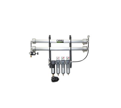
All-in-one packages include GF centrifugal water separator, NMD magnetic condensate drain, GFN 1.0 and 0.01-micron coalescing filters, and GFN AC activated carbon filter with no electricity required.
Key Specs:
Purity
95 to 99.9%
Flow Rate
8 to 2500 scfh
Added Feature
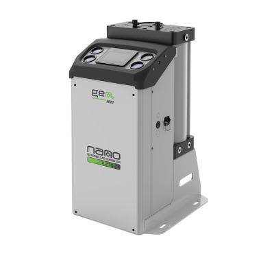
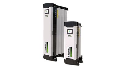
Wall-mountable System
Product Documentation
- Brochures
- Certificates
- General Arrangement Drawings
- Pre Filtration Diagram
- Technical Paper
- User Guides
- Worksheet
Features
Composed of hundreds of thousands of hollow fibers separate nitrogen from air through a process known as selective permeation
Compact and lightweight design provides horizontal or vertical placement in tight spaces with wall mounting brackets included as standard
Specifications of Our Models
Nitrogen Generator Model |
Inlet Air |
Air Inlet Requirement and Nitrogen Flow by Model (scfh) |
||||||
|---|---|---|---|---|---|---|---|---|
psig |
99.9% (0.1%) |
99.5% (0.5%) |
99% (1%) |
98% (2%) |
97% (3%) |
96% (4%) |
95% (5%) |
|
NMG 115 |
100 |
8 (1) |
15 (1) |
23 (1) |
29 (1) |
38 (2) |
49 (2) |
56 (2) |
125 |
12 (2) |
21 (2) |
32 (2) |
42 (2) |
56 (2) |
67 (3) |
77 (3) |
|
150 |
13 (2) |
24 (2) |
35 (2) |
45 (2) |
63 (3) |
77 (3) |
91 (3) |
|
200 |
20 (3) |
35 (3) |
56 (3) |
70 (3) |
95 (4) |
113 (4) |
134 (4) |
|
NMG 130 |
100 |
16 (2) |
30 (2) |
46 (2) |
58 (2) |
76 (4) |
98 (4) |
112 (4) |
125 |
24 (4) |
42 (4) |
64 (4) |
84 (4) |
112 (4) |
134 (6) |
154 (6) |
|
150 |
26 (4) |
48 (4) |
70 (4) |
90 (4) |
126 (6) |
154 (6) |
182 (6) |
|
200 |
40 (6) |
70 (6) |
112 (6) |
140 (6) |
190 (8) |
226 (8) |
268 (8) |
|
NMG 163 |
100 |
32 (5) |
63 (5) |
84 (5) |
130 (6) |
165 (7) |
204 (8) |
243 (9) |
125 |
44 (7) |
87 (7) |
116 (7) |
176 (8) |
226 (9) |
278 (11) |
328 (11) |
|
150 |
50 (8) |
101 (8) |
134 (8) |
197 (9) |
257 (10) |
314 (12) |
388 (13) |
|
200 |
73 (12) |
146 (12) |
194 (12) |
293 (13) |
388 (15) |
459 (17) |
529 (18) |
|
NMG 1126 |
100 |
64 (10) |
126 (10) |
168 (10) |
260 (12) |
330 (14) |
408 (16) |
486 (18) |
125 |
88 (14) |
174 (14) |
232 (14) |
352 (16) |
452 (18) |
556 (22) |
656 (22) |
|
150 |
100 (16) |
202 (16) |
268 (16) |
394 (18) |
514 (20) |
628 (24) |
776 (26) |
|
200 |
146 (24) |
292 (24) |
388 (24) |
586 (26) |
776 (30) |
918 (34) |
1058 (36) |
|
NMG 1317 |
100 |
159 (26) |
317 (26) |
423 (26) |
600 (29) |
776 (32) |
953 (36) |
1130 (39) |
125 |
212 (35) |
424 (35) |
565 (34) |
812 (38) |
1059 (43) |
1306 (48) |
1518 (52) |
|
150 |
238 (40) |
476 (40) |
635 (38) |
918 (41) |
1200 (48) |
1447 (52) |
1730 (58) |
|
200 |
357 (60) |
715 (60) |
953 (57) |
1341 (60) |
1765 (70) |
2154 (78) |
2542 (85) |
|
Specifications |
|
|---|---|
Inlet & outlet connections |
½” NPT |
Design operating pressure range |
100 to 200 psig |
Design operating temperature range |
41 to 113°F |
Pressure drop |
7 to 10 psig |
(1) This information is for general information purposes only. For additional technical specifications, refer to the product brochure, technical data sheets, and/or user guides. Technical specifications are subject to change.