At nano, we sell Refrigerated and Desiccant Compressed Air Dryers. We’ll help you decide which dryer is right for your air compressor.
Topics:
Introduction
- Refrigerated Dryers
- Cycling
- Non-Cycling
- Variable Speed
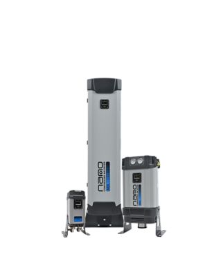
- Desiccant Dryers
- Heatless
- Externally Heated
- Blower Purge
What Does a Compressed Air Dryer Do?
Compressed air equipment has one big enemy: condensation. As your system works to provide you with a steady stream of compressed air, you need a compressed air dryer to dry out the moisture. Compressed air dryers work in different ways to remove the condensation so that the compressed air is cleaner and safer for your production workers, and extends the life of your machinery.
Industries that rely on dry, sanitary air include:
General Manufacturing
Medical Dental
Biotech
Pharmaceutical
Food Packaging
Laser Cutting
Woodworking
The Different Drying Processes
Your best type of compressed air dryer needed depends on your output, and should work together with your compressed air system as one large unit to manage condensation. We explain the three types of dryers below, and which applications they serve best.
These compressed air dryers work just as you suspect: they cool the compressed air low enough to condense any moisture so it can drain out of the compressed air system. These products are some of the most common in the industry, due to their ability to cool the incoming air to around 35°F and reheat the air as it leaves the dryer to around 35 to 50°F.
There are three types of refrigerated dryers:
Cycling
Non-Cycling
Variable Speed
Cycling
If the idea of a constantly-running machine doesn’t sound so appealing, a cycling dryer is a worthy consideration. Once a specific temperature is reached, the compressed air dryer cycles off. They are another energy-efficient option for your compressed air systems.
Deciding Factors
Pros:
Energy efficient
Cons:
May have more dew point fluctuations
How They Work
Cycling compressed air dryers save energy and money by utilizing dual transfer technology (DTT). The silica dry thermal mass stores the cold energy and keeps the dew point at the desired temperature, at which point the dryer will turn off. Once the temperature of the dry thermal mass begins to rise, the refrigerant compressor cycles on.
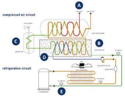
A - Hot, moist compressed air enters the separate air to air heat exchanger where it is precooled
B - Precooled compressed air then enters the air to refrigerant evaporator where it reaches its coldest point and achieves its lowest dew point
C - Condensed moisture is being removed by an integrated moisture separator and condensate drain prior to reentering the air to air heat exchanger where incoming hot air reheats the exiting cold compressed air
D - The refrigerant comes into contact with both the silica dry mass and the compressed air inside the air to refrigerant evaporator
E - If demand drops and compressed air flow rate is reduced, the refrigerant compressor cycles off and the silica dry mass is employed to continue drying the air. THIS is dual transfer technology (DTT)
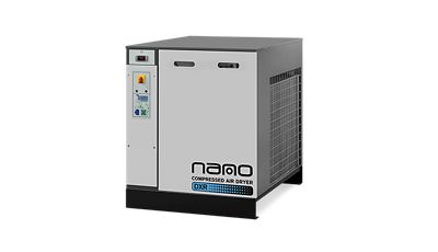
Non-Cycling
A non-cycling refrigerated compressed air dryer creates a consistent and continuous volume of compressed air, with the ability to achieve excellent dew point performance and save energy.
Deciding Factors
Pros:
Reliable dew point
Cons:
Always on and operating
How They Work
Non-cycling compressed air dryers work by moving the hot, humid air away from the compressed air system, and into the surrounding refrigerant. The refrigerant is a cooling liquid, so the moisture that is pulled from the system is cooled to around 35°F/2°C quickly. Cooling this moist air causes it to condense, and the water collects before getting discarded through drainage.
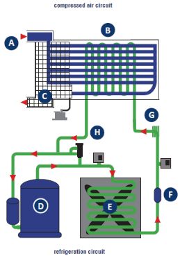
A - Hot, moist compressed air enters the pre-cooler section of the 3 in 1 heat exchanger where it is precooled by the exiting dry air
B - Precooled compressed air then enters the air to refrigerant evaporator where it reaches its coldest point and achieves its lowest dew point
C - Condensed moisture is being removed by an integrated moisture separator and zero air loss condensate drain prior to reentering the air to air heat exchanger where incoming hot air reheats the exiting cold compressed air
D - The refrigerant compressor pressurizes the returning refrigerant gas
E - An air cooled condenser removes the heat from the refrigerant and condenses it back to a liquid state
F - the refrigerant filter ensures that there is no water or particulate circulating through the system
G - the DXR uses a capillary tube for expanding the refrigerant. Having no moving parts ensures the reliability of the system
H -a hot gas bypass is used to ensure the optimal temperature is maintained in the heat exchanger preventing freezing and ice formation in the unit
Variable Speed
Variable speed compressed air dryers use a refrigerant circuit and heat exchangers to cool compressed air so that it condenses the moisture in the air. They can provide a pressure dew point (PDP) as low as +37.4°F/3°C and consume no compressed air in the process.
Deciding Factors
Pros:
Precise cooling capacity
Cons:
More sensitive to external heat and moisture
How They Work
Unlike non-cycling dryers which run continuously at full speed, variable speed refrigeration compressors only run at the speed required to dry your process air to the dew point set point of the dryer. Dryer demand is a function of both required air flow and ambient conditions. Unless both of these variables are at their maximums at the same time, there are energy savings to the had. The nano R6 line takes advantage of this savings opportunity by significantly reducing power consumption to match actual demand.
A - Hot, moist compressed air enters the separate air to the air heat exchanger where it is precooled
B - Precooled compressed air then enters the air to refrigerant evaporator where it reaches its coldest point and achieves its lowest dew point
C -The moisture is collected by the integrated water separator and evacuated by the electronic zero loss drain
D - Variable speed refrigerant compressor increases the refrigerant pressure while matching the flow rate to the dryer load
E - Electronic hot gas bypass valve allows for precise dew point control
F - Condenser coverts the high pressure refrigerant to a liquid (air cooled shown)
G - Refrigerant filter protects the entire system from water and solid particles refrigerant filter protects the entire system from water and solid particles
H - Electronic thermostatic expansion valve reduces the refrigerant temperature
I - Separator prevents any liquified refrigerant from entering the compressor
J - Outlet flow switch stops the refrigeration circuit when no air flow is detected
Desiccant compressed air dryers rely on a process called adsorption to remove condensation from a compressed air system. Different than absorption, which takes in water, adsorption works by pulling water out out the air and into the desiccant material.
At nano, we sell three types of desiccant dryers:
Heatless
Externally Heated
Blower Purge
Heatless
Heatless desiccant dryers uses a unique back-and-forth process that allows them to use its own generated dry air to remove water vapor from its desiccant material. When the material fills up with condensate, the air flows switch, allowing it to dry out again. Regenerating the desiccant over and over provides significant reliability.
Deciding Factors
Pros:
Generate very low dew points (as low as -94°F)
Cons:
Initial cost is higher compared to refrigerated dryers
How They Work
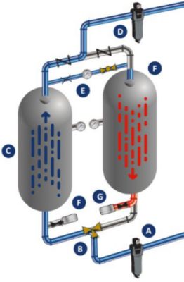
In a heatless desiccant air dryer, one tower is drying the compressed air while the other is regenerating, or eliminating the water vapor it has collected so it can be used to dry again. The two towers switch back and forth so one is always drying while the other is regenerating or in standby.
A - An included 0.01 micron pre-filter removes all particulate, liquid water, and oil aerosols to 0.01 ppm.
B - Clean, saturated air enters the inlet valve which directs it to one of the desiccant towers.
C - Compressed air travels through tower A for 5 minutes, and moisture vapor is adsorbed to -40°F pdp or lower.
D - A final filter removes particulate to 1.0 micron or better
E - Less than 15% purge air expands through an orifice and regenerates tower B
F - After 3.5 minutes, the purge exhaust valve closes, tower B repressurizes, and then is ready for adsorption to begin
G - At the 5-minute mark (fixed cycle), tower A exhaust valve opens to regenerate. A PLC controls all operations, and extends the dryer cycle. This reduces compressor energy, wasted purge air, and valve wear and tear.
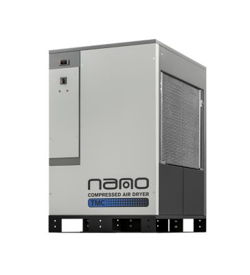
Externally Heated
Just as you would expect by the name of this type of desiccant compressed air dryer, the externally heated models use an electric heater to heat the dry purge air so it can then regenerate the desiccant beds.
Deciding Factors
Pros:
Less energy compared to heatless desiccant dryers
Cons:
Will need to replace the desiccant material more frequently
How They Work
A - Compressed air flows through the pre-filter to remove oil, and then enters the online Tower 1 through valve (A)
B - Air moves upward, where the desiccant removes moistyre from the air stream. The majority of clean, dry compressed air exits valve (B) and cycles through the after filter to then flow downstream
C - During the drying process, a small amount of the clean air exiting alve (B) travels to Tower 2 (shown in regeneration mode) to assist in the regeneration process
D - To regenerate Tower 2, valve D opens and the tower is depressurized to near atmospheric pressure.
E - Once Tower 2 is fully regenerated, valve (C) will close, repressurizing Tower 2 to line pressure with the slight airflow coming through valve (B)
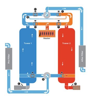
F - Next, valve C will open to depressurize Tower 1 and valve (A) will switch (not pictured), directing wet incoming air to Tower 2 for drying while Tower 1 is regenerating the desiccant bed
G -This process will repeat continuously every 4 hours unless the Energy Management System is extending the drying time perdiod during low load conditions to a maximum of 12 hours each cycle. the energy Management System continually monitors the mid-bed humitidty level in the drying tower to save energy by extending the drying cycle (up to 12 hours)
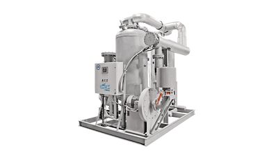
Blower Purge
The blower purge dryers take the same process a step further by using a combination of heat and ambient air to further reduce (or even eliminate) purge air usage to regenerate the desiccant beds.
Deciding Factors
Pros:
nano models reduce purge air rate to an average of 1-2%
Cons:
Hot discharge air needs to be piped away from dryer
How They Work
A - Compressed air flows through the pre-filter to remove oil and then enters the on-line Tower 1 through valve (A).
B - Air moves upward, where the desiccant removes moisture from the airstream and lowers the dew point. The majority of clean, dry compressed air exits valve (C) and cycles through the after filter to the rest of the system.
C - Tower 2 (shown in regeneration mode) depressurizes to atmosphere through an angle seat valve and muffler (D).
D - Valves (E & F) open and the heater turns on.
E - The high efficiency blower pulls in ambient air, moving it through the immersion heater and check valve. The ambient airstream passes through valve (F) and flows downward through the moist desiccant in Tower 2, collecting water vapor before exiting valve (E) and exhausting to atmosphere.
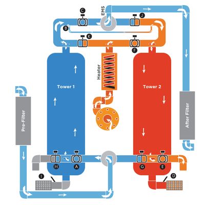
F - Once Tower 2 exhausts, and the regeneration tower reaches its set point, the heater turns off. This happens regardless of whether the cycle is finished as an energy savings feature of the EMS.
G - A small amount of air exits Tower 1 through a slipstream (B), where it will join Tower 2 to repressurize and cool the tower.
H - Ten minutes prior to vessel switchover, the Parallel Cooling Mode will begin (not pictured). Valve (E & H) will close and valves (A & G) will open, allowing incoming air to flow through both towers. This minimizes dew point spikes associated with heated dryers. Parallel Cooling Mode requires no purge air.
I - At the end of Parallel Cooling Mode, valve (G) will open, valve (A) will close, and place tower 2 online (not pictured). The EMS Settings will determine if this is at a fixed time interval or Demand Control Cycle based on outlet dew point sensor readings.
J - Operations will switch and Tower 1 will be regenerated.
Final Checklist
In order to find the right compressed air dryer for your needs, you’ll need to check a few key specifications for your production requirements. We’ve listed a few things to consider when purchasing a new dryer:
Desired pressure dew point
Maximum air flow
Inlet air pressure
Inlet air temperature
Ambient air temperature (and water temperature if dryer is water-cooled)
Installation environment of the dryer